Leave Your Message

How to Choose a Belt Counterweight Scale in 2026

In 2026, choosing a Belt Counterweight Scale is less about finding the lowest quoted price and more about matching the system to the conveyor, material, and operating routine. A scale may work on a clean, steady belt but struggle as feed rates, vibration, or buildup change. Small details matter. Before comparing models, record belt width and speed, expected throughput, material type, and the accuracy needed for daily decisions. These measurements offer a useful starting point, not a guarantee.

The right selection also depends on installation quality, calibration access, service support, and how clearly the supplier explains performance limits. Ask for documented accuracy conditions, commissioning steps, maintenance intervals, and advice for your conveyor layout. Check that the weighing frame, load cells, speed sensor, and integrator work as a complete system. This helps prevent a common mistake: judging a scale by its display or brochure specification alone. I would not assume one model suits every site; even careful guidance can miss a problem that appears only during inspection. This guide explores practical questions for comparing designs, estimating maintenance needs, and checking supplier claims before purchase. The aim is dependable measurement, with uncertainty made visible rather than hidden.
How to Choose a Belt Counterweight Scale in 2026

Understanding How a Belt Counterweight Scale Measures Material Flow

How to Choose a Belt Counterweight Scale in 2026

Understanding How a Belt Counterweight Scale Measures Material Flow

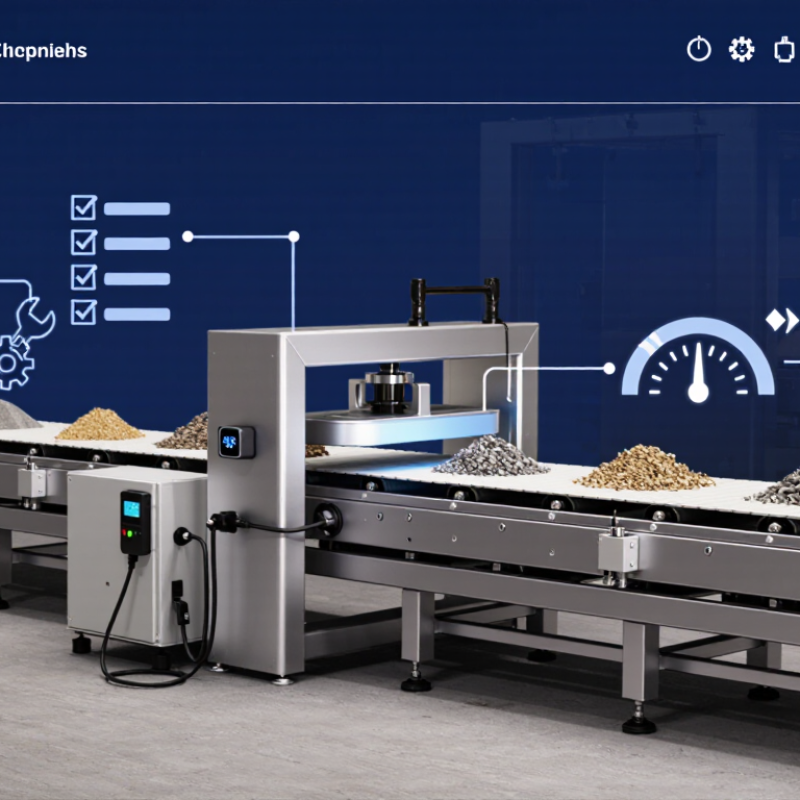
A belt counterweight scale estimates material flow while a conveyor runs. Material rests on the belt and passes over a weighing section. There, weigh idlers transfer the load to a sensing frame. Depending on the design, a counterweight helps balance or control force on that frame. The exact arrangement varies, so check the equipment drawings before comparing models.

The scale combines belt loading with belt speed. Its sensors measure the material’s weight over a known belt length, while a speed sensor tracks how quickly that length moves. The system multiplies the load per unit length by belt speed to calculate flow rate. A totalizer adds those readings over time.

That sounds simple. In practice, alignment, belt tension, vibration, and material buildup can all affect the signal. Small shifts matter.

When evaluating a scale, consider the conveyor’s speed range, belt width, expected load, and material behavior. A steady stream of dry aggregate is easier to measure than sticky material that clings to idlers. Ask how the system is calibrated and how often the belt should be checked under operating conditions.

Dust changes things. Calibration also has limits: a careful procedure cannot compensate for a damaged idler or a drifting speed sensor. It’s easy to focus on the counterweight mechanism and overlook those basics. That deserves a second look.
Defining Capacity, Accuracy, and Operating Requirements

A belt counterweight scale should be selected around the work it will actually perform, not just its maximum rated capacity. Estimate normal and peak flow in tonnes per hour, then check belt speed and material load against the scale’s operating range. A unit sized too close to the limit may struggle during surges; one sized far too high may provide poor resolution at low flow. A little margin helps.

Accuracy depends on more than the load cells. Belt tension, alignment, vibration, material buildup, and changing belt speed can all affect readings. Define the accuracy needed for process control or inventory tracking, and ask how it is verified under realistic conditions. Check the recommended calibration method and whether test weights or material tests are practical at your site. Specifications can look neat on paper; real material rarely behaves so neatly.

Operating conditions matter. Note the belt width, incline, ambient temperature, dust, moisture, and available installation space. Consider access for cleaning and inspection, too. If workers must reach around guards or remove heavy covers, routine checks may be delayed. That detail is easy to miss. Review maintenance intervals, signal connections, and how readings integrate with existing controls. A short site assessment, including observed flow variations, can reveal requirements that a datasheet will not.

Assessing Belt Conditions and Counterweight Compatibility

Before selecting a belt counterweight scale, inspect the conveyor under normal operating conditions, not only when it is stopped. Look for uneven sag, worn edges, damaged splices, carryback, and material buildup near the pulleys. These details can affect belt contact and produce readings that seem stable but do not reflect actual operation. Check the splice, too. Note the belt width, speed, idler spacing, and whether the belt tracks consistently under load. A clean belt may behave differently once wet fines cling beneath it; a brief inspection can miss that.

Check the tensioning arrangement and available counterweight travel. Compare the scale’s required contact force with the belt and frame limits. Too little force can cause intermittent contact, while too much may increase wear or disturb belt tracking. Confirm clearance during startup and shutdown, and allow for expected belt movement as load and temperature change. Small details matter. Record measurements and compare them with the equipment documentation or a qualified conveyor technician’s guidance before installation. Field conditions are messy, and an initial estimate may need adjustment after a loaded trial.

How to Choose a Belt Counterweight Scale in 2026 - Assessing Belt Conditions and Counterweight Compatibility

Example field-assessment data for evaluating conveyor belt condition, scale suitability, and take-up counterweight compatibility.
Assessment Dimension Example Field Data What the Data Indicates Selection or Compatibility Check
Belt width 1,000 mm The belt width sets the available scale-frame width and helps determine suitable weigh-idler geometry. Choose a scale frame and weigh idlers designed for the measured belt width; verify that the frame fits the conveyor structure.
Belt speed 1.8 m/s, measured during steady operation Speed affects material throughput and the speed signal required for mass-flow calculation. Confirm that the speed sensor and integrator support the actual operating-speed range and any planned speed variation.
Belt construction and condition Rubber-covered, 4-ply fabric belt; no visible edge damage; localized cover wear near the loading area Construction and wear can affect stiffness, tracking, and repeatability at the weighing station. Record belt type and condition; address significant wear, damage, or uneven stiffness before commissioning or calibration.
Belt tensioning arrangement Gravity take-up with a vertically travelling counterweight A gravity take-up can help maintain belt tension, but its force and movement must suit the conveyor design. Identify the take-up arrangement and pulley reeving. Do not infer belt tension from counterweight mass without accounting for the mechanical arrangement.
Counterweight mass Measured assembly mass: 420 kg The mass produces gravitational force, but the resulting belt tension depends on the take-up geometry, friction, and number of supporting belt parts. Check the conveyor design calculations and take-up arrangement. Confirm that the scale installation does not alter the intended belt tension.
Counterweight travel Available vertical travel: 750 mm; observed operating position leaves about 260 mm in both directions Remaining travel provides room for belt stretch, take-up movement, and operating changes. Verify that the scale and any nearby guards, cables, or structures do not restrict take-up movement or create a collision risk.
Belt sag at proposed weighing span Measured sag: 8 mm over a 1,000 mm idler span (0.8% of span) Sag influences the relationship between belt loading and the force measured by the weigh frame. Compare sag with the scale supplier’s installation requirements and keep belt tension and operating conditions stable during calibration.
Idler spacing and condition Three adjacent idler stations at 1,000 mm spacing; rollers turn freely with no visible shell damage Consistent, serviceable idlers around the scale support repeatable belt geometry. Check idler alignment, rotation, and spacing. Use the scale design’s specified weigh-idler arrangement and avoid worn or misaligned rollers.
Belt tracking Approximately 12 mm lateral movement during the observation period; belt remains on the pulley face Tracking variation can change the load distribution across the weigh frame and affect measurement stability. Correct persistent mistracking and verify belt position through the full operating cycle before final calibration.
Belt splice Vulcanized splice; no visible lift or separation; splice passes the proposed scale station periodically A splice can produce a transient signal as it passes over the weighing area, especially if its mass or stiffness differs from the belt. Inspect the splice and include its passage in repeatability checks. Follow the scale’s calibration procedure for belt-related effects.
Conveyor loading profile Material loading is centered under steady operation; occasional off-center surges observed during startup Uneven or changing loading can affect measurement stability and may expose tracking problems. Assess loading under normal and startup conditions; improve chute alignment or loading distribution where needed.
Weigh-frame alignment and clearance Proposed frame location is level; no contact with stringers or nearby structure during unloaded belt movement Mechanical contact or installation stress can transfer unwanted forces to the weighing elements. Ensure the weigh frame is installed as specified, is free from unintended contact, and has adequate clearance throughout operation.
Operating and maintenance access Access available to inspect the take-up, weigh idlers, and load-cell area after isolation Safe access supports routine inspection and helps identify changes that can affect scale performance. Plan for safe isolation and access to moving parts; install guarding and follow site safety procedures.

Important: The values above are illustrative field data, not universal acceptance limits. Confirm permissible belt sag, frame configuration, load-cell capacity, counterweight forces, and calibration procedures against the conveyor design and the selected scale’s technical requirements.

Comparing Sensors, Controls, Calibration, and Integration

How to Choose a Belt Counterweight Scale in 2026

Compare the load sensor, speed pickup, controller, and plant interface as one measurement chain. A load cell must match the weighbridge arrangement and expected material load. The speed sensor should track the belt itself, not a slipping drive component. Check that the controller records alarms, zero changes, and totalized weight. Small details matter. A clear screen is useful, but reliable timestamps and accessible raw readings are better when a result needs investigation.

Calibration depends on installation as much as instrument quality. Check belt alignment, idler condition, tension, and material buildup before testing. OIML Recommendation R 50-1:2014 defines belt-weigher accuracy classes including 0.2, 0.5, 1, and 2. Use the class required for your process, then confirm performance through suitable tests under operating conditions. NIST Handbook 44, Section 2.21, provides technical requirements and test procedures for belt-conveyor scale systems. A calibration certificate alone is not proof that a scale remains accurate after belt repairs or seasonal changes. That part is easy to overlook.

Tips: Ask for a documented zero test and a material test using a verified reference quantity. Confirm that scale data can reach your control system without manual re-entry. Keep the test records with maintenance notes; the paperwork can be imperfect, but missing dates make trends hard to trust.

Evaluating Installation, Maintenance, and Lifetime Cost

How to Choose a Belt Counterweight Scale in 2026

Evaluating Installation, Maintenance, and Lifetime Cost

A low purchase price can hide expensive installation work. Before choosing a belt counterweight scale, check conveyor width, belt speed, idler spacing, loading conditions, and access for mounting. Poor alignment or unstable belt tension can undermine readings, even with quality components. Include structural changes, wiring, commissioning, and production downtime in the initial estimate. Small details matter.

Maintenance costs continue after installation. Budget for routine inspection, calibration, cleaning around the weighbridge, and replacement of wear-prone parts. The U.S. Department of Energy’s Operations & Maintenance Best Practices Guide (2010) reports that predictive maintenance programs can reduce maintenance costs by 25–30% across industrial settings. That figure is a broad benchmark, not a guaranteed saving for a belt scale. Still, it shows why service access and condition checks belong in a lifetime-cost comparison.

Tips: Ask for a site-specific installation plan and a clear calibration schedule. Compare the expected cost over several years, including labor, spare parts, downtime, and recalibration. A spreadsheet helps, though its assumptions may be imperfect. Revisit them after the first year; actual belt conditions can differ from the design case.